DM105 Rotary
This module connects two knobs, four buttons, and an OLED display to the LIN bus.
Prototype
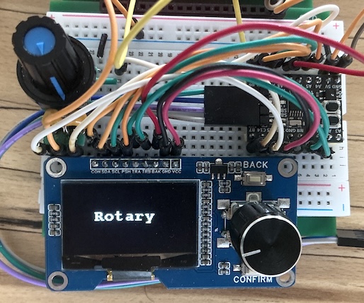
The initial protoype was built on a breadboard, using an STM32C011 board from WeAct Studio, a combined rotary encoder + 2 buttons + 128x64 OLED board, and one more separate rotary encoder. All parts came from AliExpress.
This 20-pin µC has just enough pins to connect each of the two encoders to its own hardware timer. The timers are configured in "Quadrature Encoder" mode: they'll automatically handle the incoming pulses without losing track and without any CPU involvement.
A knob counts 20 pulses per revolution: only the lower 6 bits of the timer counts are used.
Each knob can be pressed as "button" and there are two more buttons, labeled "CONFIRM" and "BACK". So that's two 6-bit counts and 4 on/off buttons, for a total of 16 bits.
The plan is to have the top-left knob select a parameter and the right one its value.
Info
The OLED display is connected and initialised, but not yet used or responding to LIN packets.
LIN device
This module responds as slave ID 1 on the LIN bus. When queried, it sends 2 bytes:
- byte 1: right knob pressed (b7), confirm (b6), right knob position (b5..b0)
- byte 2: left knob pressed (b7), back (b6), left knob position (b5..b0)
Cable version
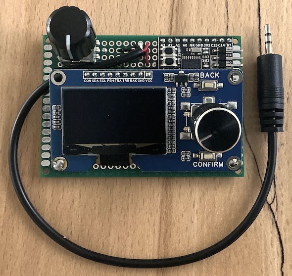
I'm constructing a more permanent setup. It includes a cable with a 2.5mm audio plug as power + LIN bus connection. This board is a bit large for an expansion base, but more importantly: when connected with a cable, these knobs can be placed where they're most convenient, away from all the breadboard jumpers.
Since LIN is indeed a bus, several such devices can be connected in parallel, as long as they each respond to a different ID.