G4-Scope
This is an exploration into the combination of analog and digital "computing". The aim is to show electrical signals as graph on a screen, i.e. to implement an oscilloscope. The first constraint is that it must fit on a 7x3 or 7x5 cm PCB so that it can be turned into a module later. The second constraint is that it must be doable for me :) - I don't have any formal electronics design training. That's really the point of this: to learn how a "scope" works.
Hardware
A STM32G431CB µC is used as the brains: its two ADCs can sample at up to ≈ 5 Ms/s, the CPU clock goes up to 170 MHz, it has 32 KB RAM, and there's 128 KB of flash memory. There's enough here for an extensive exploration and implementation.
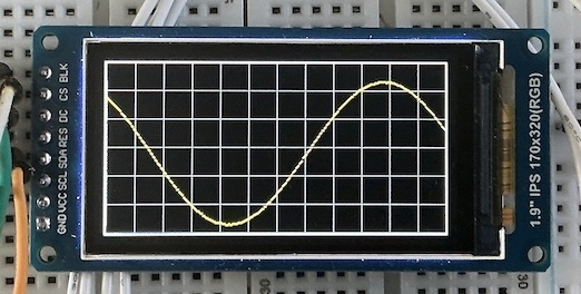
The display is a small 1.9" 320x170 pixel display. Just enough to display a "graticule" area with 12 divisions across and 6 divisions vertically.
The G4-Scope is controlled by buttons and one or two rotary encoders, but these will need to be on a separate module. There's no way to fit these on one PCB with the display.
For development, a Black Magic Probe is used, using an STM32F411 "Black Pill" board.
That, plus a breadboard and some wires, is about it. The total cost with parts from AliExpress was no more than about €30, as of mid-2026.
Once the basic design and build works, an analog front end of some kind will need to be added. But that's a bit further down the road ...
Software
On the software side, it's all based on PlatformIO and JeeH. I'm developing this on MacOS, but Linux and Windows should work equally well. See JeeH's getting started for details.
One step at a time
There are a lot of moving parts in this project. From figuring out a "good" development cycle to implementing and debugging the many different hardware details for high-speed signal acquisition and visualisation. This G4-Scope is bound to be a pretty long adventure.
All software development is based on the source code in this area: https://codeberg.org/jcw/dobb/src/branch/main/apps/g4-scope/.
Blinking LED
The first build verifies that the G431 has power and is properly connected to the Black Magic Probe (BMP), and that the LED blinks once compiled and uploaded. It's based on this code:
blink.cpp
The command to build and upload is:
Console output via RTT
See the JeeH info about RTT for details. This needs a serial connection to the BMP to display messages. That connection can then be kept open across all uploads: very convenient!
console.cpp
Sample output on the debug console, i.e. the BMP's serial USB port:
Note
This same source code structure will be used in all the following "gradual enhacement" examples.
DAC + ADC check
Next step: read out the ADC. The built-in DAC can feed different input voltages as a first test. It looks like in analog mode mode ADC and DAC can be inter-connected on one pin:
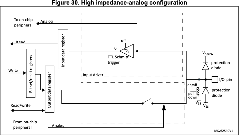
Unfortunatelt, JeeH's built-in ADC driver is not quite up to it. It's a simple implementation for ADC1, not for ADC2 (connected to DAC1's output). So for now, I'll jumper A4 to A0.
dac2adc.cpp
#include <jee.h>
#include <jee/hal.h>
using namespace jeeh;
#include "defs.hpp"

int main () {
    initBoard();

    Pin::config("A4:A");
    dac::init(); // currently hard-coded for DAC1, output pin A4
    adc::init(); // currently hard-coded for ADC1
    msWait(2); // TODO needs > 1 ms settling time, but why?

    // this code needs a jumper between DAC out (A4) and ADC in (A0)

    const uint16_t vals [] = {
        0, 1000, 2000, 3000, 4000, 4095, 4000, 3000, 2000, 1000, 0,
    };

    for (auto e : vals) {
        dac::set(e);
        msWait(1);

        logf("%4d => %4d %4d %4d", e,
            adc::read(1), adc::read(1), adc::read(1)); // A0 is ADC1 channel 1
    }

    while (true) { led.toggle(); msWait(500); }
}
Sample output, with different DAC values and three quick ADC conversions:
dac2adc: STM32G431xx @ 170 MHz (v7.0.9-13-gc89bf101)
   0 =>   11    0    0
1000 =>  960  927  931
2000 => 2016 1977 1982
3000 => 3087 2968 2969
4000 => 3936 3936 3936
4095 => 3983 3992 3992
4000 => 3936 3936 3936
3000 => 2951 2972 2969
2000 => 1927 1982 1980
1000 =>  927  927  931
   0 =>    0    0    0
It works: the DAC voltages are converted back to digital by the ADC. The measurements are a few percent off, and it looks like the top value is never reached. The DAC buffer is probably not strong enough to drive an ADC with a minimum sample time (it needs a low-impedance input to quickly charge/discharge the sample-and-hold capacitor).
Warning
With fastClock() in defs.hpp disabled, the results are a bit different.
All ADC readings are now much closer to the expected values:
Continuous DAC output
For more tests involving the ADC, a stable signal of some kind would be useful. This can be generated with the DAC and a DMA channel in circular buffer mode to continuously feed it. A hardware timer can set the pace at which the DMA feeds new values to the DAC.
But first I need a sine wave ...
CORDIC
For the sake of using as much of the µC's built-in hardware as possible, I'm generating the sine wave using the built-in CORDIC hardware. From the reference manual:
The CORDIC coprocessor provides hardware acceleration of mathematical functions (mainly trigonometric ones) commonly used in motor control, metering, signal processing, and many other applications.
cordic.cpp
Sample output:
cordic: STM32G431xx @ 170 MHz (v7.0.9-14-g6699c955)
     0                                +
 12539                                            +
 23170                                                      +
 30273                                                             +
 32767                                                               +
 30273                                                             +
 23170                                                      +
 12539                                            +
     0                                +
-12539                    +
-23170          +
-30273   +
-32767 +
-30273   +
-23170          +
-12539                    +
     0                                +
Yep, it's a sine wave. And it's in full 16-bit resolution, more than enough for a 12-bit DAC.